Civil 3d How to Get to Drawing Units Dialog Box
Article two in a serial
Units are Key in AutoCAD
To be on a offset-name, expert-buddy basis with AutoCAD, I believe that y'all need to thoroughly sympathise units.
A fisherman, to be outstanding at fishing, needs to understand the nature of h2o, lakes, and the sea. It's the same with AutoCAD. All of our created objects swim in a sea of units.
We'll focus on length units in this article. Angular units will exist discussed in a futurity post.

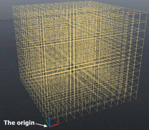
Illustration of the three-D Grid used by AutoCAD
In the commencement article of this series, we discussed the absolutely central part of units in AutoCAD. I've linked that article Here if y'all'd similar to review it.
We saw how AutoCAD organizes its universe into an imaginary three-dimensional grid. All of the objects placed in it are organized by their ten, y, and z coordinates. Those coordinates chronicle back to the origin, which is at the 0, 0, 0 location where all of AutoCAD's internal measurements begin. Here'southward the animated video I made of the grid: STOMP!

17th-Century map of the universe with Earth at the center
This origin betoken is literally the center of the universe to AutoCAD, fifty-fifty though, equally a designer, I may usually be unaware of its location relative to my work.
AutoCAD doesn't much intendance what real-globe units that you (the designer) accept in mind for your project. Exercise you like inches? Millimeters? Cubits? Furlongs?Low-cal years? Whatever, says ACAD. To AutoCAD, it's all about units.
Information technology'southward our job as designers to exist articulate and consistent about units as they're used in our projection.
The actual real-earth length measurement of a unit of measurement is just of secondary importance to the software. It'south really upward to the states, as designers, to exist clear, and to stay consistent, on the nature of the units every bit they're used in our project.
Two Places to Set Upwards Units
In that location are ii critical places in an AutoCAD project where nosotros need to advisedly set the units:
- Drawing Utilities and
- Dimension Styles.
These ii roles, while related, are actually quite dissever. The setting of one has no effect whatsoever on the other. What works well in the first may non be appropriate in the second, and vice versa.
The two roles are aimed at dissimilar audiences. The designer sees the results of the unit settings fabricated in the Cartoon Utilities dialog box. The builder or manufacturer who receives the drawings sees the results of the unit settings that the designer makes in the Dimension Styles dialog box.
Drawing Utilities is where units get defined for the direct, two-way communication between the AutoCAD software and us (the designers). The Properties dialog box is the principal place that AutoCAD software "talks" to united states of america, the designers. When you check the properties of a line or other object, how does the length appear? Does it show up with feet, inches and fractions? Or does it announced every bit simply a number, possibly with decimals?
The Listing command'south output is another place where the unit settings in Drawing Utilities affect the display of lengths. The Expanse and Volume displays are affected by the type of length unit of measurement setting.
Very importantly, this Cartoon Utilities setting controls the default unit which is assumed by AutoCAD when yous type in a number (like 36) for a distance or length.
Dimension Styles is where nosotros control how units appear in our dimensions. These dimensions appear in the printed documents and tell the architect what sizes we look them to produce in the physical objects.
I'll address setting up units in Dimension Styles in an upcoming post.
Choosing Unit Type and Precision Settings
Within the definition of the project's units, at that place are ii main settings for us to consider:
- Type and
- Precision
You say you want your house's walls laid out using meters every bit a measurement organization? Peachy. We'll choose Decimal units equally the type. It's important to note that AutoCAD volition not automatically append "cm" (significant centimeters) or "mm" (millimeters) onto the units' display. Again, it's up to the designer to keep rail of the type of metric unit that she intends to be the default unit in the drawing.
If you cull Architectural units as your type, AutoCAD will help you out by displaying an apostrophe or double quotation marks after the unit quantity in the Properties.
Now tell me — how many decimal places practice you want to see in the properties box? In the dimensions? And practise you want the building's concrete foundations laid out—and dimensioned—to the same level ofprecision equally the kitchen cabinetry? Probably not.
These are the kind of unit-related considerations that the designer needs to address when setting up units for a projection. Ideally, the designer will have a custom AutoCAD template (DTE file) where all of these decisions will be stored for use in the next project. Of course, even the best template file needs to exist reviewed and updated periodically.

Setting the project'south units in Drawing Utilities
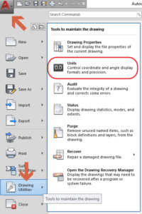
The first identify where we need to specify the type of units that we want to use for a project is in the Drawing Utilities. Again, this is where we control how the units will appear in the Properties dialog, the Listing command'due south output, and other internal locations. The settings can exist plant past clicking the Big Ruddy A (Application Browser) button and then following the bill of fare to Units.

Drawing Units dialog box
Opening the Drawing Units dialog box shows you diverse controls used to specify the Length and Bending units (epitome at left). Hither we will focus on length.
Expanding the Length Type selector gives y'all the following options:
- Architectural (meaning feet, inches, and fractions). Mainly used in the United States. Also known as "Royal" units.
- Decimal (which can mean meters, centimeters, millimeters, or many other types of units).
- Engineering (combines feet and decimal inches)
- Partial (inches and fractions, with no anxiety. Footless.)
- Scientific (using exponents)
Let'southward look at these i at a time.
Using the Architectural Unit Blazon
When y'all select Architectural units, the software translates lengths and distances into feet, inches, and fractions in its output to the designer. An apostrophe designates anxiety, and double quotation marks indicate inches.
The format of Architectural units that we input to AutoCAD is not the same as the output units' format. In AutoCAD's output to the designer, a sample length might exist: 12′-iii 1/2″. To input that aforementioned length into AutoCAD, the syntax changes. The designer is expected to type that length like this: 12'3-1/2. Go figure.
Weird Syntax
This makes some sense when you consider that AutoCAD from Version i.0 has always used the [SPACEBAR] key to be equivalent to the [ENTER] key. So typing that space betwixt the inch number and the fraction (in 12′-3 i/ii″) would throw you out of the input office of the procedure before you could get the fraction typed. That's how I justify the weird syntax required by AutoCAD for its input of Architectural unit quantities.
Using Architectural units, also known as Imperial units, the default unit that AutoCAD assumes for designer input is inches. Say you're executing a COPY or Movement command. Blazon in 36 for the move distance, with no unit type specified, and AutoCAD moves your object 36 inches, not feet.
Fractions are rounded to whatever the precision level is set to be. The AutoCAD options are:
i/ii, i/4, i/eight, 1/16, 1/32, 1/64, ane/128, or 1/256 of an inch.
Using Decimal, Applied science, Partial, or Scientific Unit Type
With Decimal unit type chosen, the default unit could be meters, centimeters, or just about annihilation imaginable (other than feet, inches, and fractions).
In civil engineering and surveying workplaces in the U.S., the default unit of measurement would be decimal anxiety. In a U.Due south. auto shop, it would ordinarily be decimal inches. In Europe it could be either meters, centimeters, or millimeters, depending on the industry that y'all're working in.
Engineering unit type: I don't know of any industry that uses a combination of feet and decimal inches. Seems foreign. About equally strange as Architectural units. A sample: 30′-2.375″.
Fractional unit type: The cabinet-edifice industry in the United states uses what AutoCAD calls Fractional units (inches and fractions, simply no anxiety). A sample: 36 1/two″.
The Scientific unit type might be useful for very large or very small work. Maybe for astronomical-calibration projects, or designing microscopic nanobots. A sample: 10.1467E+01.
By the mode, I'm told that companies that design and build microchips use mils as the standard unit for their design drawings and manufacturing. A mil equals one-thousandth of an inch. In SI (International Standard) units, 1 mil is equal to ii.54E-5 meters.
This all may seem to be basic stuff, and for many experienced users it is. Still, I think it'south helpful to think near the style that AutoCAD sees the universe. Past doing this, we can marshal our thinking with the internal processes of the software.
This understanding prepares us to respond effectively to special or unexpected challenges that ascend.
Thank you for reading! Delight share in the comments nearly your feel with unit-related matters. And every bit always . . .
Keep on CADDing!🙂
Marker
(Visited 1 times, 1 visits today)
Source: https://bestcadtips.com/autocad-units-part-2/